Physics of Current Flow in Testing Tools

Understanding the physics of current flow in testing tools is essential for accurate measurements. Electric current, driven by potential difference, moves through conductors while facing resistance. Tools like multimeters measure voltage, current, and resistance according to Ohm’s Law. Conductors allow efficient flow, while insulators protect against hazards. Digital and analog devices each have unique benefits for various applications. If you explore further, you’ll uncover advanced techniques for optimizing your electrical testing skills.
Key Takeaways
- Electric current flows through conductors due to the movement of electrons, influenced by factors like resistance and temperature.
- Ohm’s Law (V = I × R) defines the relationship between voltage, current, and resistance, essential for accurate measurements with testing tools.
- Multimeters measure voltage, requiring correct settings and probe connections to ensure accurate readings aligned with circuit specifications.
- Conductors enhance circuit efficiency, while insulators prevent current flow, minimizing hazards and maintaining safety during electrical testing.
- Advanced testing techniques, such as oscilloscope analysis, provide insights into voltage changes over time, improving diagnostic accuracy in complex circuits.
Fundamental Principles of Electric Current
Have you ever wondered how electric current flows through wires to power your devices? It all starts with the movement of charged particles, primarily electrons.
When you connect a device to a power source, like a battery or outlet, a potential difference—or voltage—creates an electric field. This field pushes electrons through the conductor, generating current.
The flow of current is measured in amperes and is influenced by factors such as resistance and temperature. Resistance, which opposes the flow of electrons, is determined by the material of the wire and its thickness.
The flow of current, measured in amperes, is affected by resistance, which depends on wire material and thickness.
As the current travels, energy is transferred to your device, allowing it to function. Understanding these fundamental principles helps you grasp the basics of electric current flow. Additionally, ensuring proper testing with fuse testers is crucial for maintaining electrical safety in your devices.
Measuring Voltage: The Role of Multimeters
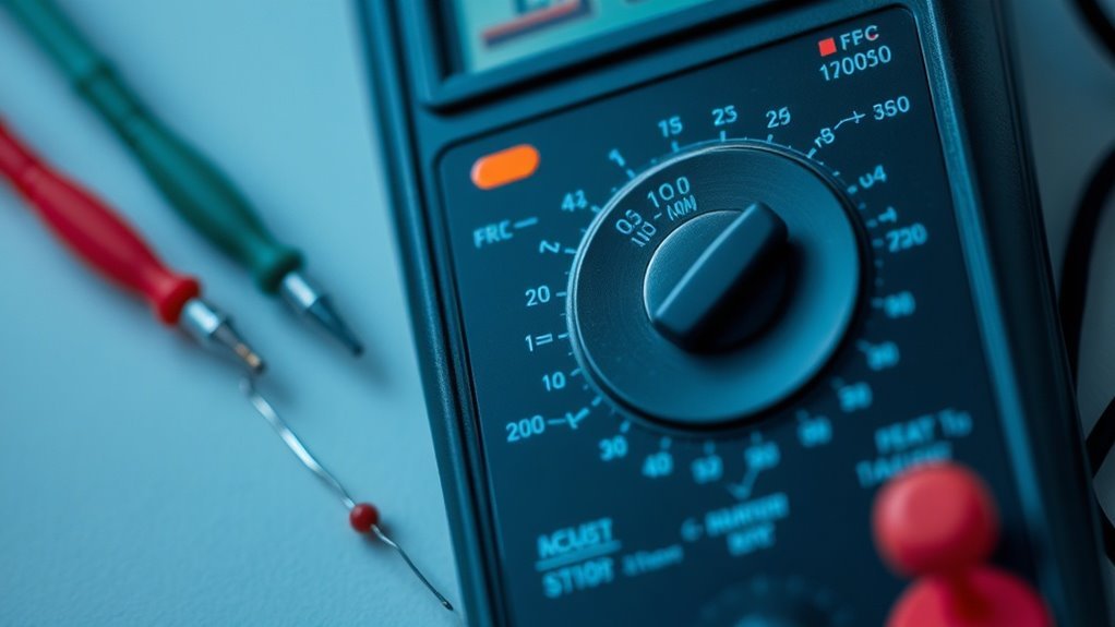
When you’re troubleshooting electrical circuits, measuring voltage is essential, and a multimeter is the tool for the job. This handy device measures the electrical potential difference between two points in your circuit.
To use it, set the multimeter to the voltage setting—either AC or DC, depending on the circuit you’re testing. Then, connect the probes: the red one to the positive side and the black one to the negative side.
The display will show you the voltage reading, helping you diagnose issues. A properly functioning circuit should have voltage readings consistent with the design specifications. Additionally, understanding the principles behind measurements can further enhance your ability to interpret the readings accurately.
If you notice significant discrepancies, it might indicate faults, breaks, or even shorts in the circuit, guiding you in your troubleshooting efforts.
Understanding Ohm’s Law in Testing Tools
Ohm’s Law serves as a fundamental principle in understanding electricity, especially when using testing tools like multimeters. It defines the relationship between voltage (V), current (I), and resistance (R) with the simple formula V = I × R.
When you measure voltage across a circuit using a multimeter, you’re directly applying this law. If you know the resistance, you can easily calculate the current flowing through your circuit. Understanding this relationship helps you diagnose issues effectively when using testing tools.
For instance, if you detect high resistance, you can anticipate a decrease in current based on Ohm’s Law. It’s essential to grasp these concepts to utilize your testing tools efficiently and interpret the data they provide.
Conductors, Insulators, and Their Impact on Current Flow
Understanding how current flows through different materials is key to grasping how circuits work. Current flows easily through conductors like copper and aluminum, allowing electrical devices to function properly.
In contrast, insulators like rubber and glass resist this flow, preventing unwanted discharge.
Here’s how conductors and insulators impact current flow:
- Conductors enhance efficiency and minimize power loss.
- Insulators protect against electrical hazards and maintain safety.
- Material choice affects circuit design and performance.
Recognizing the roles of these materials can help you make informed decisions in testing tools and circuit applications.
The Functionality of Oscilloscopes in Current Analysis
One of the most valuable tools for analyzing current flow in circuits is the oscilloscope. This instrument allows you to visualize electrical signals, showing how currents change over time.
By connecting the oscilloscope probes to your circuit, you can capture waveforms representing voltage fluctuations and current behavior. You’ll be able to observe amplitude, frequency, and any distortions in the signals.
With its user-friendly interface and various settings, you can adjust the time base and voltage scale for detailed analysis. This flexibility helps you detect issues, such as noise or fluctuations, that might affect circuit performance.
Ultimately, mastering the oscilloscope lets you enhance your understanding of current flow, leading to more effective circuit designs and troubleshooting.
Safety Considerations in Electrical Testing
When you’re working with electrical testing, safety should always be your top priority.
Using personal protective equipment, proper tools, and being aware of hazardous voltage can protect you from serious risks. Additionally, utilizing tools such as fuse pullers and circuit testers is crucial for enhancing safety during electrical work.
Let’s explore these essential safety considerations further.
Personal Protective Equipment
Safety isn’t just a guideline; it’s an essential part of electrical testing, and wearing the right personal protective equipment (PPE) can make all the difference.
When you’re working with electrical systems, protecting yourself against potential hazards is vital. Here are three key pieces of PPE you shouldn’t overlook:
- Insulated Gloves: They help safeguard your hands from electric shock while allowing you to handle various tools.
- Safety Goggles: Protect your eyes from sparks, debris, and other flying particles that could cause injury during testing.
- Flame-Resistant Clothing: This type of apparel minimizes the risk of burns if an electrical arc occurs.
Proper Tool Usage
Using the right tools is essential for conducting safe and effective electrical testing. Not only do proper tools enhance accuracy, but they also minimize safety risks. Always verify your tools are rated for the specific applications you’re using them for, and regularly inspect them for wear. Don’t forget to use insulated tools when testing live circuits.
Here’s a quick reference table to guide you on some essential tools and their uses:
| Tool | Purpose | Safety Tips |
|---|---|---|
| Multimeter | Measure voltage/current | Verify probes are intact |
| Insulated Screwdriver | Tighten/remove fasteners | Use only on non-live circuits |
| Clamp Meter | Measure current without breaking circuit | Verify proper clamp placement |
Hazardous Voltage Awareness
Electrical testing involves inherent risks, particularly when it comes to hazardous voltages.
Being aware of these dangers is essential for your safety and the safety of those around you.
Here are some key points to remember:
- Always identify live circuits before starting any testing procedure to avoid accidental contact.
- Use appropriate personal protective equipment (PPE), such as insulated gloves and safety goggles, to reduce the risk of electric shock.
- Follow proper lockout/tagout (LOTO) procedures to guarantee that equipment is properly shut down and can’t be accidentally energized during testing.
Digital vs. Analog Testing Devices: A Comparative Analysis
While both digital and analog testing devices serve essential roles in measuring electrical parameters, their fundamental differences can greatly impact how you approach testing in various situations.
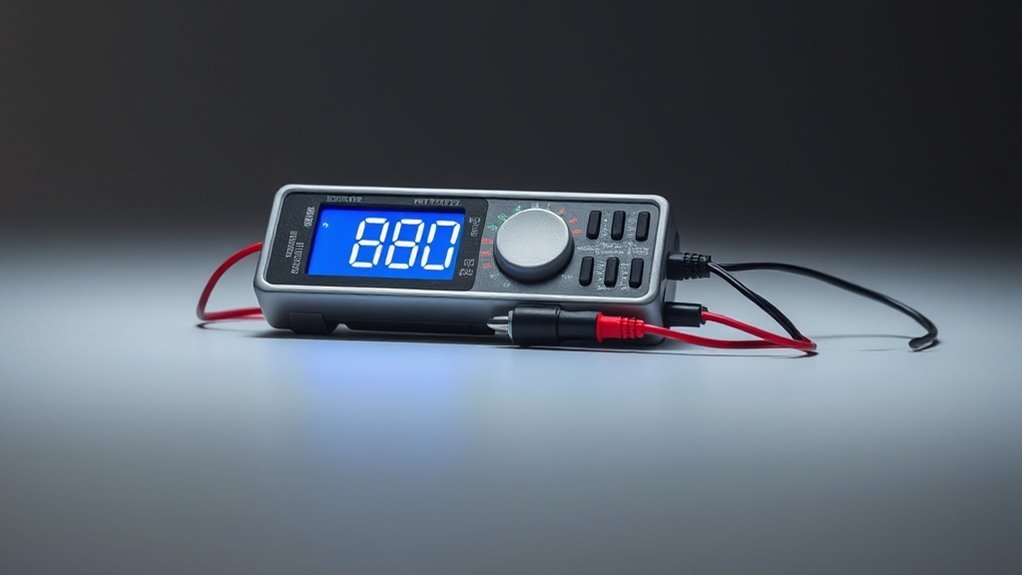
Digital devices, like multimeters, provide clear numerical readouts, making it easier for you to interpret results quickly. They often come equipped with features like data logging and automatic ranging, which can enhance your efficiency in complex tasks.
Digital multimeters deliver clear numerical displays for quick interpretation, often featuring data logging and automatic ranging to boost efficiency.
On the other hand, analog devices, such as needle voltmeters, offer real-time movements that can help you detect rapid fluctuations in voltage or current. They’re also less susceptible to sudden spikes interrupting readings.
In your choice of device, consider accuracy, response time, and specific testing requirements to determine which type best fits your needs.
Advanced Testing Techniques for Complex Circuits
When tackling complex circuits, employing advanced testing techniques can greatly enhance your troubleshooting effectiveness.
These methods help you pinpoint issues that traditional tools might miss.
Here are a few techniques to evaluate:
- Oscilloscope Analysis: Visualize voltage changes over time to diagnose irregular waveforms or signal integrity issues.
- In-Circuit Testing (ICT): Perform non-intrusive measurements on components within their operating environment, identifying faults without disassembling circuits.
- Boundary Scan Testing: Utilize JTAG to access internal registers, enabling you to test the functionality of components without physical contact.
Questions
How Do Temperature Changes Affect Current Flow in Testing Tools?
Temperature changes can affect current flow in testing tools by altering resistance. As temperature rises, resistance typically decreases, leading to increased current. Conversely, lower temperatures can increase resistance, which reduces current flow through the tools.
What Is the Impact of Frequency on Current Measurements?
Imagine measuring current in an electric motor. Higher frequency can cause inaccurate readings due to impedance variations. It’s essential to calibrate your equipment appropriately; otherwise, you might observe misleading values that impact your analysis.
Can Humidity Influence Electrical Testing Results?
Yes, humidity can influence electrical testing results. Increased moisture levels may lead to corrosion or conductive paths, affecting readings. It’s important to control humidity for accurate measurements in your electrical testing environments to guarantee reliable results.
How Do Battery Types Affect Measurement Accuracy in Tools?
Battery types can notably impact measurement accuracy in your tools. If you’re using a lithium-ion battery, for example, you might notice more reliable readings than with weaker alkaline options—shouldn’t you consider that in your testing?
What Maintenance Is Required for Testing Equipment?
You should regularly calibrate your testing equipment, clean connectors, and check batteries. Inspect cables for wear or damage, and store tools in a dry, safe place to guarantee they function accurately and last longer.
Conclusion
In summary, mastering the physics of current flow in testing tools not only empowers you to diagnose electrical issues but elevates you to a domain of expertise few can claim. Whether wielding a multimeter or an oscilloscope, your understanding of voltage, Ohm’s Law, and the behavior of conductors and insulators will enhance your precision in testing. So, gear up and immerse yourself in these principles—your skills will illuminate the darkest corners of electrical circuits like a thousand suns.