Understanding Continuity Testing in Circuits
Continuity testing is an essential method to guarantee your electrical circuits are functioning correctly by checking for uninterrupted connections. You’ll use a multimeter to send a small electric current through the circuit, confirming whether there’s a complete pathway for current flow. This process helps you identify issues like open circuits or broken wires, enhancing safety and reliability. If you want to explore the tools and steps for effective continuity testing, there’s more to discover.
Key Takeaways
- Continuity testing checks if an electrical circuit is uninterrupted, ensuring reliable connections and circuit integrity.
- A multimeter or continuity tester is essential for performing tests and identifying circuit faults.
- Continuous verification helps detect open circuits, short circuits, and broken wires that disrupt current flow.
- Proper safety measures, like ensuring circuits are powered off, are crucial to prevent electric shock during testing.
- Documenting testing results aids in efficient troubleshooting and improving overall electrical safety.
What Is Continuity Testing?
When you think about electrical circuits, understanding whether there’s a complete path for current to flow is essential, and that’s where continuity testing comes in.
Continuity testing is a straightforward process used to determine if an electrical circuit is uninterrupted. By using a multimeter or continuity tester, you can check for any breaks or faults within the circuit. The tester sends a small amount of electrical current through the circuit; if it receives a signal back, it indicates that the path is complete.
This is vital for troubleshooting and ensuring safety in your electrical projects. The simplicity of continuity testing makes it a fundamental tool for both professionals and DIY enthusiasts when diagnosing circuit issues.
Importance of Continuity Testing in Electronics
Continuity testing is essential for anyone working with electronics, whether you’re a seasoned pro or just starting out. It helps guarantee that circuits function properly and that electrical connections are intact. You can quickly diagnose issues, saving time and preventing costly repairs.
Here’s a quick overview of why continuity testing matters:
| Reason | Benefit |
|---|---|
| Verifies connections | Guarantees circuit reliability |
| Identifies breaks | Prevents circuit failure |
| Saves time | Speeds up troubleshooting |
| Enhances safety | Reduces shock risk |
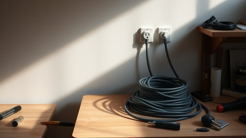
Tools Needed for Continuity Testing
To effectively test for continuity in circuits, you’ll need a few essential tools.
A multimeter is vital for checking electrical connections, and having the right test probes can make the process smoother. Additionally, visual inspection tools can help you spot issues that aren’t immediately obvious. Understanding how multimeters measure voltage can enhance your ability to diagnose problems in your circuit effectively.
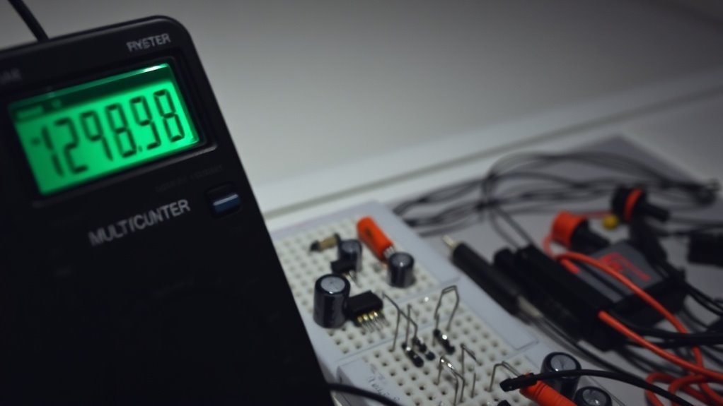
Multimeter Importance
Although testing for continuity might seem straightforward, having the right tools, especially a multimeter, is essential for accurate results. A multimeter allows you to measure resistance, which is vital in determining whether a circuit is complete. Without it, you could easily miss a break or short in the wiring.
When you set your multimeter to the continuity setting, it provides a quick and reliable way to check connections. You’ll often hear a beep when continuity is present, confirming that the circuit is intact.
Plus, it can help you troubleshoot other issues beyond just continuity, making it a versatile tool for any electronics enthusiast. So, investing in a good multimeter is definitely worth it.
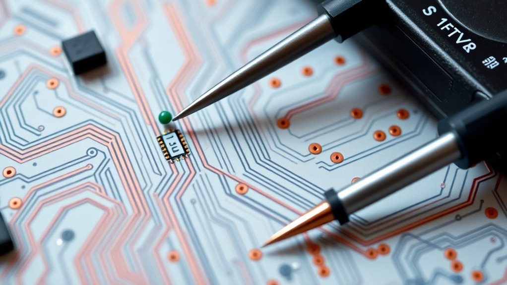
Test Probes Overview
When testing for continuity, the right test probes play a vital role in achieving accurate results. These probes primarily connect your multimeter to the circuit, allowing you to check for electrical continuity.
You’ll typically need two types: standard probes and alligator clips. Standard probes are useful for making quick connections to various points, while alligator clips allow for a secure grip on components, leaving your hands free to operate the multimeter.
It’s important to verify that the probes are in good condition, as worn or damaged probes can yield misleading readings. Always choose probes that fit the application you’re working on, so you can get the most reliable results during your continuity testing.
Visual Inspection Tools
Having the right test probes is important, but visual inspection tools also play a key role in continuity testing. These tools help you identify issues before you even make a measurement.
A thorough visual assessment can save time and prevent further complications down the line. Here are some essential tools you should consider:
- Multimeter: For measuring voltage, current, and resistance.
- Wire Strippers: To prepare wires for connection and testing.
- Screwdrivers: For accessing components and connections.
- Magnifying Glass: To spot small damages or inconsistencies on circuits.
- Flashlight: To illuminate hard-to-see areas during inspection.
Using these tools in combination with your test probes will enhance your testing capabilities and improve reliability.
Step-by-Step Guide to Performing Continuity Tests
Performing a continuity test is essential for troubleshooting electrical circuits, and following a step-by-step guide can make the process straightforward.
First, you’ll need a multimeter set to the continuity mode. Next, verify the circuit is powered off to avoid any electric shock. Touch the probes to either end of the wire or component you’re testing. If the meter beeps or shows a reading, you’ve got continuity; otherwise, there’s a break in the circuit.
For more complex setups, check connections at junctions and terminals. Document your findings for reference.
Repeat this process for different parts of the circuit to verify thorough testing. With practice, you’ll get quicker and more confident in identifying issues in the circuit.
Common Issues Detected Through Continuity Testing
When performing continuity tests, you might encounter a couple of common issues.
Open circuits can signal breaks in the pathway, while short circuits indicate unintended connections.
Identifying these problems early can save you time and trouble in troubleshooting your circuits.
Open Circuits Identification
Open circuits can pose significant challenges in electrical systems, especially since they often go undetected until they cause failures.
Identifying these open circuits is essential for maintaining system reliability. Here are some common issues you might encounter during continuity testing:
- Broken wires that disrupt current flow
- Loose connections that fail under load
- Damaged components like switches or terminals
- Corroded connectors that lose conductivity over time
- Faulty solder joints that can break easily
Short Circuits Detection
Detecting short circuits is essential for preventing damage and ensuring the safe operation of electrical systems. When you perform continuity testing, you’re on the lookout for unexpected connections that allow current to flow where it shouldn’t. A common issue is wires touching each other due to insulation failure, causing a sudden spike in current. This can lead to overheating and ultimately equipment failure.
You should also check for faulty components, like capacitors or resistors, that may create unintended paths for electricity. By identifying these problems early, you can avoid potential hazards, save on costly repairs, and keep your electrical systems running smoothly.
Best Practices for Continuity Testing
To guarantee accurate and reliable continuity testing, it’s essential to follow best practices that can enhance your results. Keeping these tips in mind will help confirm you identify issues effectively.
- Always confirm the circuit is powered off before testing to avoid injury and equipment damage.
- Use a quality multimeter or continuity tester for precise measurements.
- Verify the device’s calibration before every test to maintain accuracy.
- Inspect all leads and probes for damage or corrosion before use.
- Document your findings for future reference, helping you track changes or recurring issues.
- Incorporating tools like circuit testers can further ensure your electrical systems are functioning safely and efficiently.
Questions
Can Continuity Testing Be Performed on Powered Circuits?
You can’t perform continuity testing on powered circuits, as the live voltage can give inaccurate readings and potentially damage your multimeter. Always guarantee the circuit is de-energized before testing for continuity. Safety first!
What Is the Difference Between Continuity and Resistance Testing?
Actions speak louder than words, and continuity testing checks if a path is unbroken while resistance testing measures how much opposition to current flow exists. Both serve different purposes, so you’ll need them at different times.
How Do Environmental Factors Affect Continuity Testing Results?
Environmental factors like temperature, humidity, and corrosion can skew continuity test results. If it’s too damp or cold, you might get inaccurate readings. Always consider these variables to guarantee reliable continuity assessments in your testing.
Are There Specific Safety Measures for Continuity Testing?
Absolutely, you should always wear insulated gloves and goggles, plus guarantee the power’s off. Like a knight donning armor, you’re protecting yourself from unexpected shocks while guaranteeing your testing stays safe and reliable.
How Often Should I Perform Continuity Tests in My Circuits?
You should perform continuity tests regularly, ideally every time you install or modify a circuit. Additionally, testing after experiencing any issues or before troubleshooting can help guarantee everything’s functioning as it should.
Conclusion
In the domain of electronics, continuity testing acts as the compass guiding you through the intricate landscape of circuits. By ensuring a seamless connection, you prevent the journeys of electricity from encountering roadblocks and interruptions. Just as a bridge connects two shores, your careful testing unites components, safeguarding against unforeseen failures. Embracing these practices not only enhances your projects but also fortifies your confidence in traversing the electrifying world of circuitry.